
User-first opening: clear goals, fewer surprises
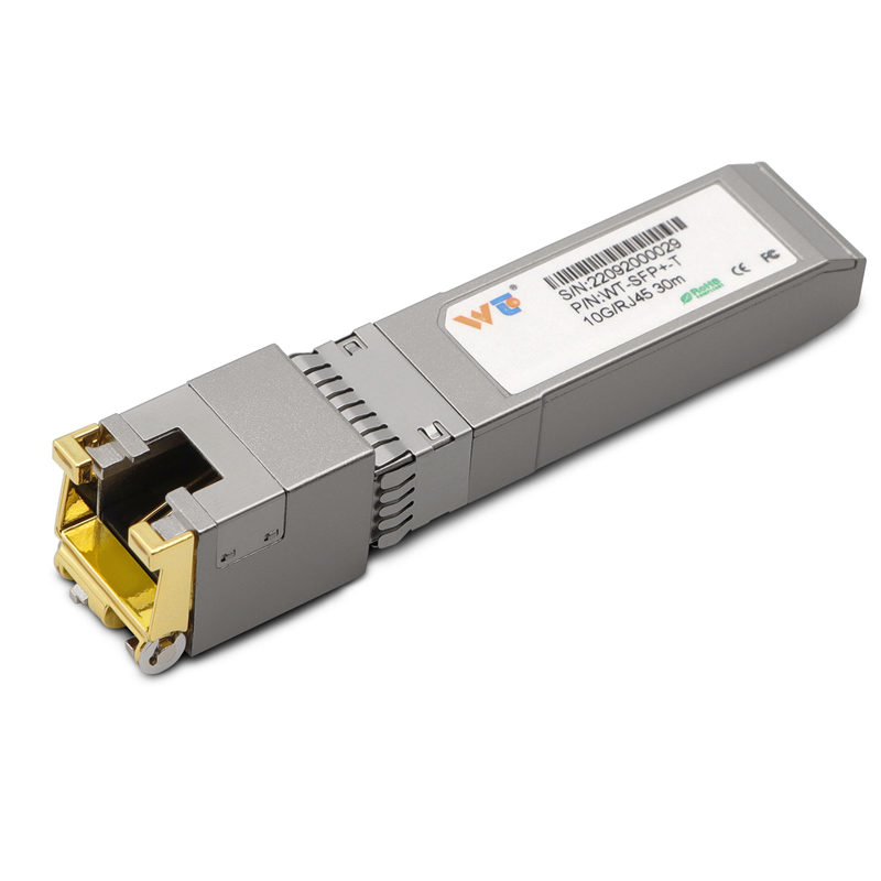
Start by picturing the people who depend on the link—network operators, colo customers, or the on-call engineer—then set a measurable uptime goal. Keep a spare sfp to rj45 transceiver on the bench if you can; it saves a late-night truck roll. This piece centers on the 100G QSFP28 LR4 transceiver and the realities of single-mode fiber deployments, but it also reminds you when a copper option like an SFP makes sense during short runs.
Prepare the site and inventory
Confirm fiber routes, rack space, and power labels before you touch an optic. Check patch panels for correct single-mode fiber labeling and remove dust caps only at the last moment. Keep a calibrated fiber microscope, cleaning wipes, and a set of transceiver ejector tools ready. Label everything so the next person knows what you did—clear documentation prevents repeated mistakes.
Inspect the transceiver and cabling
Unbox the QSFP28 LR4 transceiver and inspect for shipping damage, bent pins, or missing retainer clips. Verify the part number, serial, and DOM information against your inventory system. For single-mode fiber, confirm the LC connectors match the LR4 breakout plan and that the fiber cable has the correct attenuation spec for the intended span.

Ten-step installation sequence (concise and test-first)
Follow this order to reduce rework: 1) confirm link plan, 2) verify optics model and firmware, 3) label ports, 4) clean connectors, 5) insert transceiver gently, 6) attach cables in logical order, 7) enable port on switch with conservative settings, 8) run basic link tests (LOS, optical power), 9) run BER or RFC2544-style throughput test if required, 10) document results and stage rollback steps. Keep the test results attached to the work order for audits.
Common mistakes and how to sidestep them
Mixing multimode and single-mode fiber remains the simplest, costliest error—always check the fiber type. Mismatched transceiver firmware and switch drivers cause intermittent errors, so align firmware releases when possible. Overlooking connector cleanliness leads to measurable loss; clean, inspect, and re-test. A brief aside—don’t force a connector; if it won’t seat, stop and inspect the ferrule.
Testing that proves the link works
Measure receive/transmit optical power, check for excessive attenuation on the span, and validate link state under expected traffic. Run a short BER test or a sustained throughput test during a maintenance window. Real-world anchor: many Ashburn data centers require post-installation optical power logs and a 24-hour stability check before accepting new backbone segments, so collect logs that show stable power and error-free operation.
Compatibility and fallback options
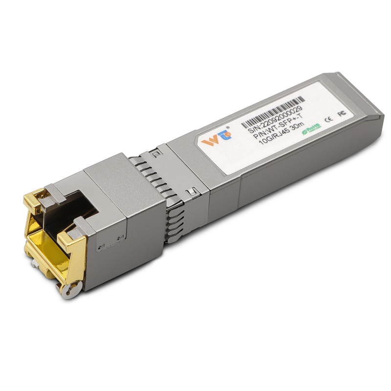
Ensure the switch supports QSFP28 LR4 modules and that breakouts—if used—match speed and lane mapping. For short-distance or temporary runs, an sfp copper transceiver can be a practical stopgap, but note copper limits and latency. Keep firmware and transceiver compatibility matrices in your toolset to avoid handshake problems.
Hand-off and documentation
Deliver a one-page summary: part numbers, fiber IDs, optical power, BER/throughput results, and rollback instructions. Train the on-call team on simple triage steps—check LEDs, verify DOM readings, and swap to a spare transceiver if initial symptoms persist. Good documentation turns installations into repeatable, low-risk procedures.
Three golden rules for selecting optics and procedures
1) Match physical layer specs first: ensure single-mode fiber, connector type, and transceiver wavelength align. 2) Validate performance with objective measurements: optical power, attenuation, and BER. 3) Plan for recovery: spares, labeled cables, and documented rollback steps. These are practical metrics that reduce downtime and simplify troubleshooting.
Trust hands-on verification, keep a spare on the shelf, and let consistent procedures protect your backbone—WINTOP. –