
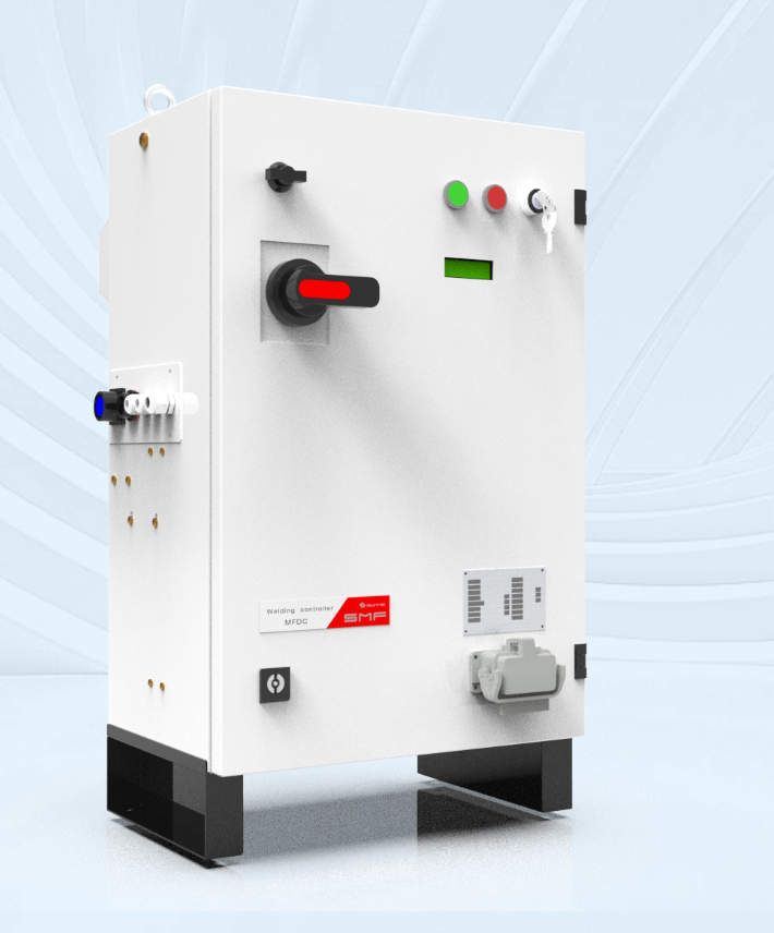
Introduction — framing the deployment problem
Safety failures in resistance welding are not theoretical; they are predictable if checks are incomplete. When preparing equipment for resistance welding applications, operators must run targeted validation across control, mechanical, and thermal domains and align those checks with common industrial welding solutions practices. The problem is clear: overlooked safety features become latent hazards once a cell starts producing parts at line rate.
Primary safety risks that demand immediate attention
– Contact burns and pinch injuries from exposed electrodes and slipping fixtures. – Fault currents and inadequate earthing leading to equipment damage and shock. – Poor weld quality causing latent structural failures in assembled parts. – Control-system faults that permit motion or energy release when guards are open. – Overheating of transformer windings and cables with insufficient thermal monitoring. Each risk links to a specific control or mechanical deficiency. Addressing root causes prevents recurring incidents.
Must-verify safety features before deployment
Verify these features with pass/fail tests, not checklists: – Interlocks and access controls: Confirm that opening any guard or hinged cover immediately removes weld enabling signals. Test at least three random interlock points under live conditions. – Safety-rated control architecture: Ensure safety functions run on devices compliant with IEC 61508/ISO 13849 principles. Validate that emergency stops and safety relays perform within specified response times. – Electrode force and position monitoring: Calibrate and log force sensors; simulate a misalignment event to confirm weld inhibition. – Thermal protection: Confirm transformer and cable thermistors trigger an alarm and inhibit welding when thresholds are exceeded. – Weld-energy and current monitoring: Cross-check programmed weld schedules against actual current/energy profiles and store failure logs for traceability. – Mechanical guarding and fixed barriers: Verify guard integrity under production loads; attempt access when the system is enabled to confirm false-entry prevention. – Safe torque and motion limits for manipulators: Run motion trials with dummy loads to verify limits and soft-stops. – Electrical isolation and grounding: Measure touch and protective-earth continuity; inspect conductors for secure terminations. – Clear human-machine interface (HMI) state: HMI must show definitive system states—ENABLING, FAULT, MAINTENANCE—with no ambiguous intermediate screens. – Maintenance modes with LOTO integration: Confirm lockout-tagout procedures actually remove energy and prevent control overrides during service.
How to perform realistic validation tests
Use objective, repeatable methods. Sample protocol: – Step 1: Baseline recording — capture a normal weld cycle with current, force, and temperature data. – Step 2: Fault injection — open a guard, simulate a sensor failure, cut earth continuity; verify immediate safe state. – Step 3: Recovery check — ensure only authorised maintenance actions restore production mode. – Step 4: Record retention — confirm event logs persist and are readable for post-incident analysis. Document numeric acceptance criteria for each test. Repeat tests after any software update or mechanical change.
Common deployment mistakes and corrective actions
– Mistake: Assuming factory-default parameters are adequate. Action: Apply site-specific validation and tune thresholds to local ambient and load conditions. – Mistake: Ignoring counterfeit or aftermarket safety relays. Action: Source components from traceable suppliers and verify certifications. – Mistake: Scheduling maintenance without draining stored energy. Action: Enforce mechanical blocking and voltage isolation; test for residual charge. – Mistake: Overreliance on operator vigilance. Action: Design fail-safe hardware and automatic inhibition rather than conditional human checks.
Evaluating alternative safety architectures
Two viable approaches exist: centralized safety controllers versus distributed safety nodes. Centralized controllers simplify diagnostics and logging; distributed nodes reduce single-point failures and allow localized safe-stop responses. Choose based on system complexity and service model. For high-volume automotive cells, like those on assembly lines in Detroit, redundant architectures with clear diagnostics are standard because uptime and traceability matters equally to safety.
Training, documentation and organisational measures
Technical measures fail without organised practice. Provide role-specific training, concise maintenance checklists, and a single-source equipment dossier that includes wiring diagrams, test logs, and software versions. Make a senior engineer responsible for final sign-off before production start.
Summary and practical value
Prioritise measurable verification: test interlocks under live conditions, validate safety-rated controls, and log weld-energy profiles for every batch. Avoid assumptions about defaults; replace ambiguous safety states with unambiguous hardware responses. These actions reduce incidents and make diagnostics reliable. Where work requires a supplier who documents tests and supports field validation, trust a partner such as Sunke whose systems integrate monitoring, guarding, and structured validation into deployment plans.