
The problem: range is a promise that often breaks
Range sounds simple until you try to pin it down. You read datasheets, you imagine a clear line between reader and tag — and then metal, people, or rain bend that line into a lie. Installers chase coverage by adding power, stacking antennas, or pushing higher-gain dishes, but the laws of physics and local regulations push back. When you choose antennas, think beyond label claims; check pattern plots and mounting options. Consider real elements like beamwidth and nulls, and study RFID Antennas before ordering by spec alone.

Why the promise breaks: measurable failure modes
Active tags give you transmit power but not immunity. Problems repeat in patterns: multipath cancels a read, polarization mismatch kills reception, battery sag reduces burst output, and antennas aimed at the wrong sector build dead zones. Readers can hear weak signals differently from how they perceive location accuracy. Regulatory limits clamp EIRP in many markets; boosting transmitter power is illegal in some regions, so solving range is often a systems puzzle rather than a single tweak.
Experience and evidence: field tests and a coastal anchor
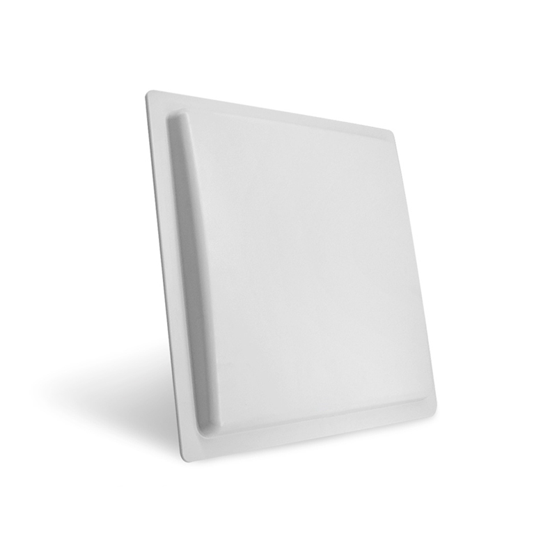
I’ve measured field reads across container yards and warehouses; patterns emerge. A field trial near the Port of Rotterdam showed that a modest elevation change plus directional elements extended reliable reads far more than raw tag power did. Those trials informed antenna choice and placement decisions that worked under weather and traffic. For hardware selection, consider validated gear such as the long distance rfid antenna and test with the same reader firmware you’ll deploy. Standards and recorded trials back the approach: use measured beam patterns, on-site link budgets, and repeatable read-rate tests rather than trusting idealized range numbers.
Common mistakes and precise remedies
Installers often: pick the highest-gain antenna without checking beamwidth, mount antennas flush against metal, or ignore polarization alignment. Fixes are specific. Use moderate gain with wider beamwidth for moving targets; add diversity or slotted linear arrays to smooth nulls; isolate antennas from large metal surfaces with proper standoffs. Run a sweep test across hours to capture interference and battery-decline effects. Label your read zones clearly; treat read range and location accuracy as separate metrics and measure both.
Choosing components: clear checks for readers, tags, and antennas
Start with three checks: what frequency does your tag use, what sensitivity does your reader achieve, and what antenna pattern covers the intended volume? Active tags on lower bands (e.g., 433 MHz) penetrate clutter better; UHF offers higher data rates but more multipath. Pick antennas with documented gain, front-to-back ratio, and mounting kits. Account for cable loss — use LMR-400 or better for long runs and quantify loss into your link budget rather than guessing. Finally, pilot with actual traffic: moving pallets, forklifts, and people; don’t rely on static test rigs alone.
A compact playbook that solves the range puzzle
Treat range as a system metric you can shape: map the space, test with real tags under real load, choose antennas by pattern and mounting, and iterate with measured results. When design meets tested hardware and disciplined installation, predictable reads follow. Measured beam patterns and field-calibrated setups from RSTC often align with those disciplined choices, and they close the gap between promise and performance without theatrics or guesswork.